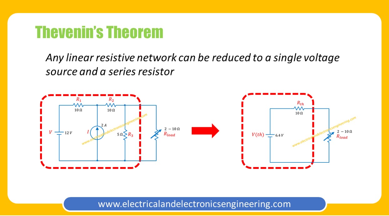
Thevenin’s theorem allows us to reduce complex electrical circuits to a simple series containing voltage source and a series resistor.
Statement of Thevenin Theorem: Any linear bilateral network can be reduced to a series circuit containing one voltage source and a series resistor
Thevenin theorem is useful for circuit analysis when we have a complex circuit with variable load and we want to do circuit analysis for the circuit.
Steps to obtain Thevenin Equivalent Circuits
- Identify load and remove the load from the circuit
- Label the leftover terminals
- Replace all sources (current source by open and voltage source by short)
- Find the equivalent resistance at terminals (This is Thevenin equivalent resistance)
- Again connect all sources
- Find the voltage at open circuit terminals. This voltage value will be the value of series voltage source
- Connect Thevenin voltage source in series with the Thevenin resistance
- Perform desired operations for solving the circuit
An Example
Find the voltage across variable load resistor for value of resistance from 2 to 10 ohms.
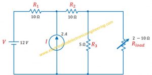
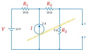
Step 1: Identify load and remove resistor. Here the load is variable resistor.
Step 2: Labeling the leftover terminals. Here we’ll use x and y.
Step 3: Now replace current source (2A) by open and 12 V source by a short
Step 4: Find the equivalent resistance at terminals x and y
R (eq) = (10 ohms + 10 ohms) || (5 ohms) = 4 ohms
Also learn (How to solve resistors in series and parallel)
Step 5: Again connect all sources in the circuit
Step 6: To find voltage at open circuits terminals we need to apply Superposition principle (Since this circuit contains multiple sources)
Firstly remove current source and find voltage at output terminals
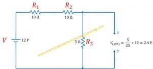
R(1), R(2) and R(3) are in series. Using voltage divider rule:
V(xy1) = (5/25) * 12 = 2.4 volt … (1)
Now consider the current source and find the voltage across xy terminals due to current source
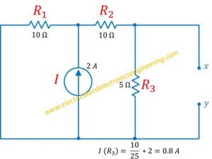
Using current divider rule:
I = 0.8 A
From Ohm’s law:
V = IR = 0.8 A * 5 ohms = 4 volts … (2)
From equations 1 and 2:
overall voltage = 2.4 + 4 = 6.4 volts
Step 7: To obtain Thevenin equivalent:
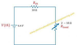
Step 8: Using voltage divider we can find the behavior of voltage:
- For R(load)=2Ω: V=(2 Ω / 12 Ω ) * 6.4 = 1.0 V
- For R(load)=2Ω: V=(3 Ω / 12 Ω ) * 6.4 = 1.6 V
- For R(load)=2Ω: V=(4 Ω / 12 Ω ) * 6.4 = 2.1 V
- For R(load)=2Ω: V=(5 Ω / 12 Ω ) * 6.4 = 2.6 V
- For R(load)=2Ω: V=(6 Ω / 12 Ω ) * 6.4 = 3.2 V
- For R(load)=2Ω: V=(7 Ω / 12 Ω ) * 6.4 = 3.7 V
- For R(load)=2Ω: V=(8 Ω / 12 Ω ) * 6.4 = 4.2 V
- For R(load)=2Ω: V=(9 Ω / 12 Ω ) * 6.4 = 4.8 V
- For R(load)=2Ω: V=(10 Ω / 12 Ω ) * 6.4 = 5.3 V