An electrical circuit is a combination of two or more components that are connected together to obtain some output. Very often the components are connected in series to form a series circuit. In this post, you’ll learn everything important about the series circuits. Let’s start it.
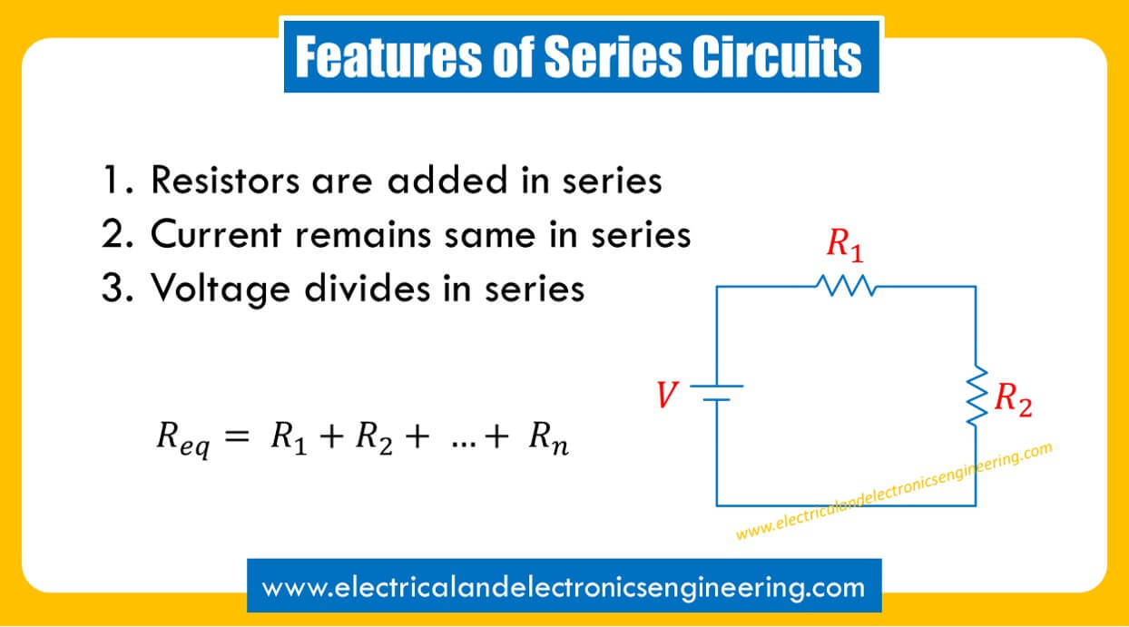
What is a series circuit and how to identify it
A series circuit is the one in which one end of two components are connected together and there is no other connection between them. Consider the circuit below:
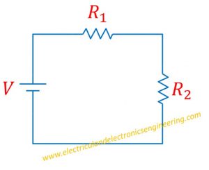
Resistor R1 connects to resistor R2 and there is no other component between them, both of these resistors are in series. Similarly, the resistor R2 and negative terminal of voltage source are connected to each other and there is no other connection between them. Resistor R2 and source V are also in series. Finally, the positive terminal of V and one end of resistor R are also in series. Since all components are in series, the overall circuit is referred to a series circuit.
How resistance behaves in series
The overall resistance of circuit is sum of individual resistors.
Let’s again consider the Figure 1.
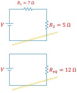
The overall resistance Req is sum of two resistors in series.
Mathematically, Req = R1 + R2
Example: Let’s assume R1 = 10 ohms and R2 = 7 ohms then Req = 5 ohms
The figure below illustrates this:
How current behaves in series
The electric current through a series circuit adjusts itself in such manner that the same current flows through all components. In actual the current is the ratio of voltage to the overall resistance of the circuit. The electrical current always remains same through series components. If 5 A current flows through resistance R2 then same 5 A will flow through 7 A current.
Suppose in the first circuit of figure 2. The value of the voltage source is 24 volts. Then current I = V/R = 24 V / 12 ohms = 2 Amps flows through the entire circuit.
How voltage behaves in series
The electrical voltage in series circuit divides between components. The higher the value of resistance is, the more voltage is dropped across it. Let’s again consider the case discussed in the previous section. From current of 2 Amps, the voltage V = IR across resistors are calculated by Ohms law:
V(1) = IR1 = 2 A. 7 ohms = 14 V
V(2) = IR2 = 2A. 5 ohms = 10 V