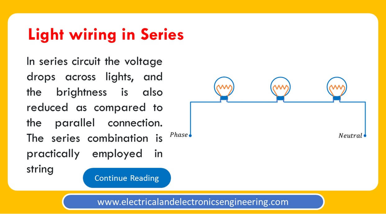
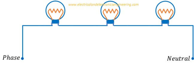
The series wiring of electrical lights involves the combination of components in such a way that phase is connected to one terminal of light, the other terminal of light connects to next light and series continues until last light whose second terminal connects to neutral.
In this post, you’ll learn the circuit diagram of light wiring in series, its impacts on brightness, the stability of the circuit, and some practical cases where we want light wiring in series.
The Circuit Diagram
The figure below displays three-light lamps wired in a series configuration. The phase is supplied to one terminal of the lamp, its other terminal connects in series to the next lamp and so on. One terminal of the last lamp is provided with the neutral link.
Given below are some facts about series circuits:
- Voltage always divides in series. For example, if LEDs having the same resistance are connected to a 9 V source, each LED will dissipate 3 volts.
- The brightness of light lowers in series as compared to parallel configuration
Practical Application
Practically series connection of lights in not employed in domestic, industrial or residential applications. However, it finds its popular use in decoration strings where multiple lights are connected in series and are directly provided the 120/230 V AC supply. In order to correctly work the sum of overall voltage drop across LEDs should equal to the overall supply.
i.e 115 LEDs each having 2-volt potential drop should be connected in series to a 230 V source.
These days the direct 120/230 V of LEDs is very rare and various electronic circuits/configurations and solid-state electronic components are employed with LED circuits for decoration purposes.