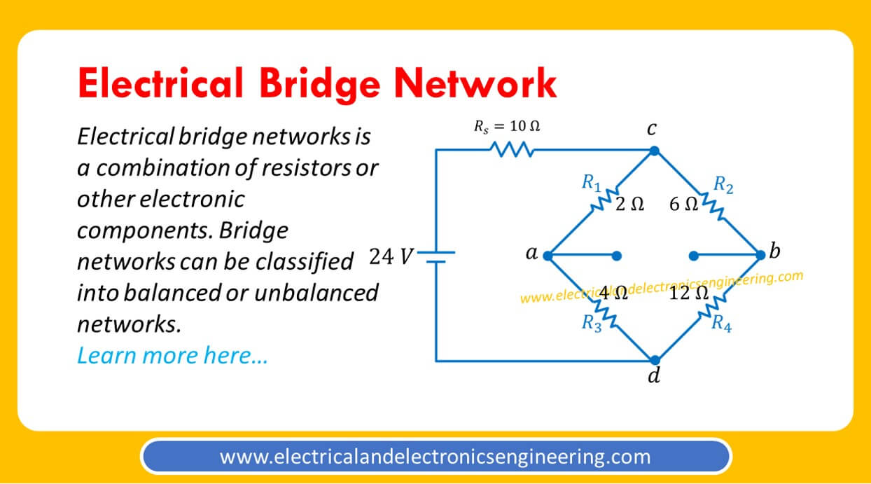
Bridge circuits are widely employed in Electrical and Electronics Engineering for measurement purposes. In this post, you’ll learn about electric bridge networks.
How it looks
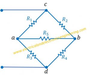
The figure below displays a 5 resistor bridge network:
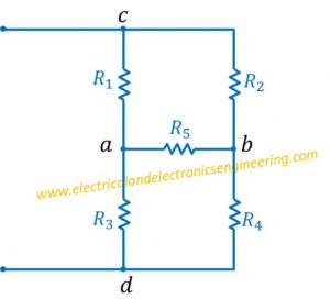
It can also be redrawn as:
Balanced vs unbalanced bridge
In above figure if R1/R3 = R2/R4 then bridge is referred as balanced bridge. If the ratio R1/R3 is not equal to R2/R4 then bridge is referred as unbalance bridge.
In a balanced bridge the current flowing through R5 is zero.
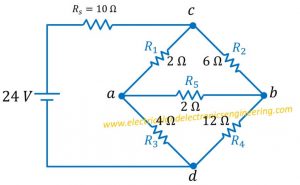
Example: Find the current flowing Rs in bridge network shown below.
Solution:
Since R1/R3 = R2/R4, zero current passes through R5.
Here we can replace the resistance R5 by an open circuit.
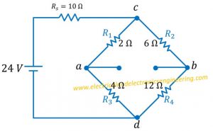
The overall resistance Rs through circuit is:
Rs = 10 Ω + {(2 Ω +4 Ω )||(6 Ω + 12 Ω )} = 10 Ω + 4.5 Ω = 14.5 Ω
I (Rs) = V/Rs = 24/14.5 Ω = 1.65 A